
How Flange Connections Work
The Parker 4-bolt flange connections conform to SAE J518 and ISO 6162-1 and -2. Flanges are proven leak-free connections especially suited for larger sizes, higher pressures, and assembly in tight quarters.
Threaded port connections, such as SAE straight thread O-ring and ISO 6149, are easy to assemble and provide 6000 psi (and higher) pressure capability up to size 3/4” and 27mm (beyond 3/4” size the pressure rating decreases and assembly torques increase).
Compared to an equivalent size, threaded port Parker 4-bolt flange connections require lower assembly torque; another advantage in tight quarters where wrench clearances are limited.
Parker Hydraulic Flange Design and Construction
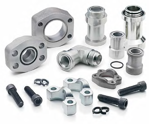
Parker 4-bolt flange products are designed to provide different methods of connecting a tube, hose, pipe or fitting to the SAE standard 4-bolt flange ports.
Flange Fittings
All Parker flange fittings (except for those with square mounting hole patterns – nomenclature code QS), are designed to conform to O-ring groove, bolt holes and bolt pattern dimensions of either Code 61 or Code 62 of SAE J518 and ISO 6162-1 (Code 61) or -2 (Code 62).
The flange adapters (Code Q1 and Q2), and flange block fittings (Codes Q1B, Q2B and QSB) have O-ring grooves conforming to dimensions in SAE J518. The flange block fittings (Codes Q1B and Q2B) have through holes for the mounting bolts conforming to SAE J518.
There is no industry standard for the bolt pattern of the square pattern block flanges with codes QSP and QSB. The flange pad fittings (Codes Q1P, Q2P, and QSP) have a flat face (no O-ring groove) and the mounting holes are tapped. Where these fittings are used, the seal is in the mating part (flange adapter, flange hose fitting, flange block fitting, etc.) as shown below.

Dimensions other than the O-ring groove, bolt holes, bolt pattern, and the flange foot print (for codes Q1B and Q2B only) are not governed by any industry standard. However, Parker product design follows common industry practice and sound engineering.
Flange Clamps
Clamps provide the holding power to the 4-bolt flange connection. They are offered in split and captive (one-piece) versions. The captive version is also offered with either drilled or tapped bolt holes. The captive flange clamp with tapped holes is used while connecting a tube to another tube or a hose.
Parker flange clamps are forged for higher strength and durability. They meet all requirements of SAE J518. The split clamps make it easy to assemble the connection in close quarters. They also make removal of the flange head component, such as a hose assembly, easy by loosening all four bolts and removing one clamp half, as shown below.

Junction Block Tees
These are solid block union fittings, used to:
- Connect two tube/hose assemblies using 4-bolt flange connections at a junction to SAE 4-bolt flange port, or
- Three tube/hose assemblies to each other
Connector Plate
Connector plates are used as a middle plate to connect two flange heads with O-ring grooves (such as two hose assemblies with flange connection ends). The flat surface of the plate provides a sealing surface on each side for the O-ring housed in the hose ends.
Spacer Plate
Spacer plates provide access to the system fluid via the gage port on the side. The plate is between the two flanges.
Plugs
Plugs provide a means to block off the 4-bolt flange port either with or without clamps, and to plug the end of a pipe (by welding).
Tank Weld Adapter
Tank weld adapters provide a means of flange connection to a fabricated reservoir or tank.
Standard Material Specs for Parker Hydraulic Flanges and Components
|
Hydraulic Flanges |
Steel |
Stainless Steel |
||
|
ASTM |
Type |
ASTM |
Type |
|
|
4-Bolt Flanges |
A108 |
C1020 |
A240 |
316L |
|
Flange Clamps |
A108 |
C1045 |
A351/A743 |
Nitronic 50 |
|
HHCS Bolts |
SAE Grade 8 |
- |
- |
|
|
SHCS Bolts |
- |
- |
A340 |
316 |
NOTE: Split flange clamps are zinc clear (or Cr6 free) chromate plated. All other steel flanges are oil dipped. Flange adapters are not plated.
How Parker Flange Connections Work
Flange connections use a static face seal (a high durometer O-ring), and clamps/bolts for holding power as shown below. The (O-ring) seal is compressed between the bottom of the groove in the flange head and the flat surface of the port or flange pad, providing a reliable soft seal.

Alternatively, a bonded seal plate is between the port face and the flat face of a flanged tube as shown below. The seal plate has a high durometer bonded rubber seal on the inside edge, which compresses between the two flat surfaces, providing a soft seal with the same reliability.

In either scenario above, a metal-to-metal contact at the outer face of the flange with the port face keeps the seal from extruding under pressure. This metal-to-metal contact is maintained by the clamping force provided by tightening the bolts via the clamps. This simple design provides several advantages over threaded port connections, such as NPTF, SAE, BSPP, ISO 6149, etc., in larger sizes:
- Ability to connect up to 5 inch O.D. tube (Code 61 only)
- Much lower tightening torque required from the four bolts compared to that required for an equivalent sized threaded port
- Less tightening torque means smaller wrenches and wrench swing clearances — providing ease of assembly in tight quarters
- Up to 6000 psi capability through 2” size (Code 62 only)
- Single seal point between tube/pipe/hose assembly and the port
- Ease of disassembly through use of split clamps
- The draw-back of the hydraulic flange connections is a larger footprint on the component than an equivalent threaded port
