Never mix different manufacturers hose and fittings or other accessories.
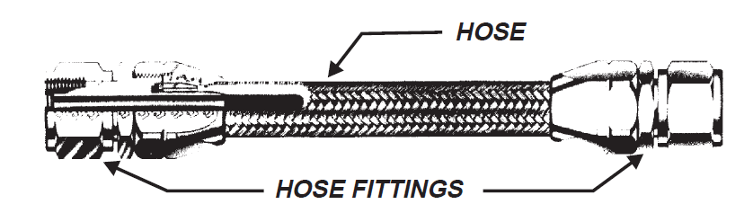
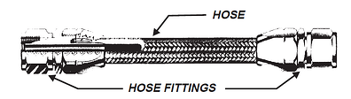
There are five parts to every hose assembly; hose, two (2) end fittings, proper assembly processing or procedure(s), and proper tooling.
Storage and Handling
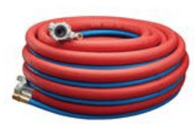
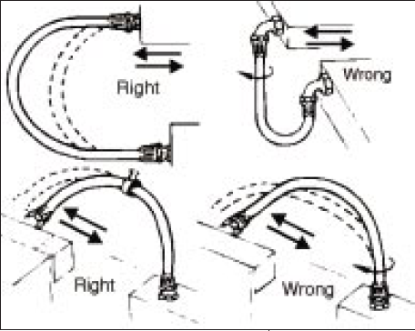
All hose assemblies whether rubber or PTFE, should always be handled with care to prevent excessive bending, twisting, and kinking. Dragging a hose on ground surfaces, using them as climbing handles and severe bending to fit cramped storage areas must be avoided. Kinking of hose occurs more easily in larger sizes and in very short assemblies.
Never step on, stand on or pull the hose.
Selection
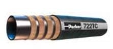
Before replacing a hose assembly, be sure to correctly identify it so the right replacement can be made. Some hoses have a lay line on the cover that gives identifying information. Hoses with a stainless steel outer braid are identified with white tape. The assembly is normally tagged as well.
Typical lay lines are repeated every nine to ten inches along the length of the hose and provide the following information:
- Manufacturer's Name and Manufacturer's Code.
- MIL-SPEC or Industry Spec Number.
- Part Number
- Dash Number (or code letter) for Size.
- Manufactured/Cure Date (if Rubber).
Use the S.T.A.M.P. rule to make sure that your hose is the correct size, that it is designed to withstand both the media & ambiant temperatures as well as pressures associated with your application. Also make sure that the inner tube of the hose you are selecting is chemically compatible with your media.
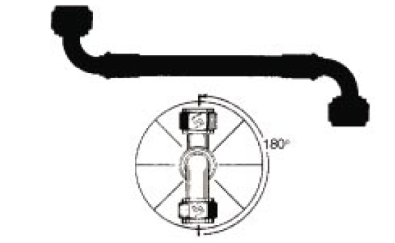
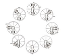
When installations require hose assemblies with elbow fittings on both ends, determine the angle between the fittings (clocking). Hold the assembly so that the nearest fitting is pointed in the 6 o'clock position. Measure the angle between the fittings counter-clockwise - that is your clocking angle. When both fittings point to 6 o'clock, this is specified as zero degrees.
Installation
1. Attach the hose to the most inaccessible end of its routing first. Finger-tighten only, so the hose is free to turn during initial installation. Hose should not be twisted on final installation.
2. Attach the other end of the hose in the same manner.
3. Properly orient the hose along its routing and install the required line support clamps.
4. Use proper torque and remember to always lubricate! Use established installation torque values or consult ARP908 for limits. Also, the flats-from-finger-tight (F.F.F.T.) method is simple to use and more consistent than measuring input force. Dissimilar materials or metals (e.g. aluminum fitting to stainless steel) require different torque and F.F.F.T. values.
Posted by Joni Scott