
Parker Air Cylinder Stroke Selection Chart
Use this Air Cylinder Stroke Selection Chart to select a piston rod for thrust/push applications. Follow these steps:
- Determine the type of cylinder mounting style and rod end connection that is required. Consult the chart below to find the "stroke factor" that corresponds to the selected specifications.
- Determine the "basic length" by using the following equation:
Basic Length = Actual Stroke x Stroke Factor
The graph is prepared for standard rod extensions beyond the face of the gland retainers. For rod extensioins greater than standard, - 3. Find the load imposed by the thrust application by multiplying the full bore area of the cylinder by the system pressure.
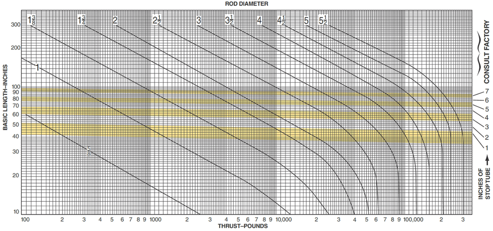
- 4. Enter the graph along the values of "basic length" and "thrust" as found above and note the point of intersection.
- A. The correct piston rod size is read from the diagonally curved line labeled "Rod Diameter" above the point of intersection,
- B. The required stop tube length is read from the right of the graph by following the shaded band in which the point of intersection is found.
- C. If the required stop tube length is in the region labeled "consult factory," submit the following information for analysis:
- Cylinder mounting style
- Rod end connection and method of guiding load
- Bore, required stroke, length of rod extension (dimension "LA" or "LAF"), if greater than standard, and series of cylinder used
- Cylinder mounting position (if angle or verticle, specify direction of piston rod)
- Operating pressure of cylinder, if limited to less than standard pressure for cylinder selected
Recommended Mounting Styles for Maximum Stroke and Thrust Loads
| Mounting Style | Rod End Connection | Case | Stroke Factor |
|
Groups 1 or 3 Long stroke cylinders for thrust loads should be mounted using a heavy-duty mounting style at one end, firmly fixed and aligned to take the principal force. Additional mounting should be specified at the opposite end, which should be used for alignment and support. An intermediate support may also be desirable for long stroke cylinders mounted horizontally. |
Fixed and Rigidly Guided | I  |
0.50 |
| Pivoted and Rigidly Guided | II  |
0.70 | |
| Supported but not Rigidly Guided | III  |
2.00 | |
|
Group 2 Style D - Trunnion on Head |
Pivoted and Rigidly Guided | IV  |
1.00 |
| Style DD - Intermediate Trunnion | Pivoted and Rigidly Guided | V  |
1.50 |
|
Style DB - Trunnion on Cap Style BB - Clevis on Cap |
Pivoted and Rigidly Guided | VI  |
2.00 |
Available Pneumatic Cylinder Styles
 |
Tie Rod Cylinders |  |
Guided Cylinders |
 |
Round Body Cylinders |  |
Rodless Cylinders |
 |
Compact Cylinders |
 |
 |
Engineering & Product Selection Information
Pneumatic Product Selection
- Pneumatic Actuators & Air Cylinders
- Pneumatic Cylinders
- Automation Products: rotary actuators, grippers, slide tables, rotary tables, escapement
- Actuator Accessories: Linear alignment couplers, flow controls, air oil tanks, rodlocks, electronic sensors, shock absorbers
Application Engineering Data
- Operating Principles and Construction
- Fluids and Temperature
- Push and Pull Forces
- Mounting Information
- Ports
- Tie Rod Supports, Stroke Data & Stroke Adjusters
- Mounting Classes
- Stop Tubing
- Stroke Selection Chart
- Deceleration Force and Air Requirements
- Cushion Ratings and Air Requirements
- NFPA Rod End Data and Piston Rods
- Modifications, Special Assemblies, Tandem Cylinders, Duplex Cylinders
- Rotary Actuator Torque Requirements
- Rotary Actuator Basic Equations
- Conversion Factors