Parker Air Cylinder Mounting Information

Parker single-rod air cylinders are available in 20 standard mounting styles. Stroke length, piston rod diameter and the method of connection to load are all important factors to consider when selecting an air cylinder for an application, as these factors will effect the cylinder's operation and service life.

Each style falls into one of three basic groups:

Group 1 - Straight line force transfer with fixed mounts that absorb force on the cylinder centerline.

 Group 1 Cylinder Mounting

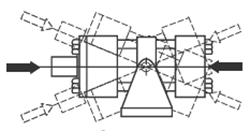
Group 2 - Pivot force transfer with pivot mounts that absorb force on cylinder centerline and permit cylinder to change alignment in one plane.
Group 2 Cylinder Mounting

Group 3 - Straight line force transfer with fixed mounts that do not absorb force on the cylinder centerline.

Group 3 Cylinder Mounting

Straight Line Force Transfer (Group 1)

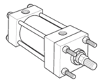
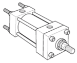
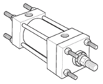
Fixed mount, centerline force-absorbing cylinders are considered ideal for straight line force transfer. The symmetrical mounts allow the thrust and tension forces of the piston rod to be distributed uniformly and keep damage from cylinder bearing sideloading to a minimum.

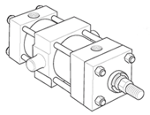
tie-rods-extended-head-end.png

Style TB

tie-rods-extended-cap-end.png

Style TC


tie-rods-extended-both-ends.png

Style TD


Styles TB, TC & TD - Tie Rods Extended

  • Designed to withstand maximum rated internal pressure
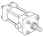
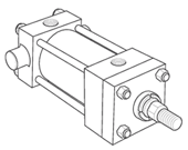
  • Can be extended and used to mount cylinder at head (Style TB), cap (Style TC) or both ends (Style TD)
  • Securely supports cylinder when bolted to the panel or machine member to which it is mounted

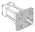
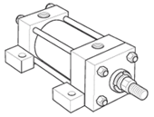
flange-mount-j.png

Style J

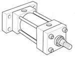
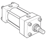
flange-mount-jb.png

Style JB


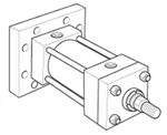
cap-rectangular-flange-mount-h.png

Style H


cap-square-flange-mount-hb.png

Style HB


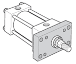
Styles J, JB, H & HB - Flange Mount

  • Choice of mounting styles at each end - head rectangular flange, head square flange, cap rectangular flange and cap square flange
  • Best used when end face is mounted against machine support member - especially when head rectangular flange (Style J) is used with major load in tension
  • Use head square flange (Style JB) mounting for applications where push forces require full rated system pressure
  • Use of cap rectangular flange (Style H) mounting is not recommended on applications where major load is in tension, except at reduced pressure
  • Use cap square flange (Style HB) mounting for applications where pull forces involded require full rated system pressure

Pivot Force Transfer (Group 2)

Pivot mounted cylinders absorb force on the centerline and should be used in applications where the machine member travels in a curved path. Clevis or trunnion mounting provides a pivot point for the cylinder to move during the work cycle.

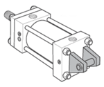
cap-fixed-clevis-mount-bb.png

Style BB


spherical-bearing-mount-fig-11.png

cap-detacable-clevis-mount-bc.png

Style BC

head-trunnion-mount-d.png

Style D

cap-trunnion-mount-db.png

Style DB

intermediate-trunnion-mount-dd.png

Style DD


Styles BB, BC, SB, D, DB & DD - Pivot Mount

  • The fixed clevis mount (Style BB) is the most widely used of the pivot force transfer types - they are used in applications where the piston rod end travels in a curved path in one plane
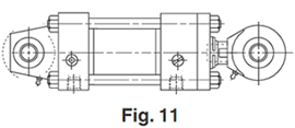
  • Cap spherical bearing mounts (see Fig. 11) are recommended for applications where the piston rod will travel in a path not more than 3° on either side of the true plane motion
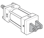
  • Cap detachable clevis mounts (Style BC) are mainly used for air service, and are longer than fixed clevis mounts in all bore sizes
  • Head trunnion mount cylinders (Style D) can typically be specified with smaller diameter piston rods when compared to cap end or intermediate trunnion mounts Stroke lengths should not exceed 5 times the bore size.
  • Cap end trunnion mounts (Style DB) are used on cylinder applications similar to fixed clevis mounts
  • Intermediate trunnion mounts (Style DD) are considered to be ideal to balance the weight of the cylinder and can be located at any point between the head or cap to suit an application - however, this location is fixed and not easily changed after manufacture

Straight Line Force Transfer (Group 3)

Side mounted cylinders do not absorb force on the centerline and have mounting lugs connected to the ends. These cylinders should be specified with a stroke length at least equal to the bore size.

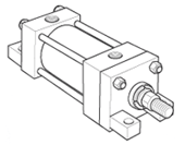
side-lug-mount-c.png

Style C

side-tap-mount-f.png

Style F

side-end-lug-mount-g.png

Style G

side-end-angle-mount-cb.png

Style CB


Styles C, CB, F, TEF & G - Side Mount

  • Side lug mount (Style C) is the most popular and reliable style of side mount cylinder because the mounting lugs are part of the head and cap.
  • Side tapped mounts (Styles F and TEF) are used when mounting cylinders side by side at minimum center-to-center distance.
  • Side end lug mount (Style G) is a narrow side mount style where the lugs are threaded to the tie rods, which also helps to hold the cylinder together while it is mounted. Side end lug mount should only be used for light- to medium-duty applications, as the end lugs are subjected to stresses that could cause premature failure.
  • Side end angle mount (Style CB) is the weakest of the narrow side mount styles, and should be limited to a maximum pressure of 150 psi and minimum stroke length of two times the bore size


Available Pneumatic Cylinder Styles

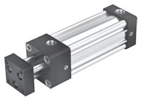
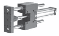
Tie-rod air cylinder - non-rotating Tie Rod Cylinders Guided Cylinders
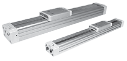
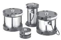
Round Body Cylinders Rodless Cylinders
Compact Cylinders    


Quote by Part Number Help with Cylinder Identification

Engineering & Product Selection Information

Pneumatic Product Selection

  • Pneumatic Actuators & Air Cylinders
  • Pneumatic Cylinders
  • Automation Products: rotary actuators, grippers, slide tables, rotary tables, escapement
  • Actuator Accessories: Linear alignment couplers, flow controls, air oil tanks, rodlocks, electronic sensors, shock absorbers

Application Engineering Data


California Prop 65 Warning WARNING: These products can expose you to chemicals including lead and/or DEHP and/or carbon black, which are known to the State of California to cause cancer or birth defects or other reproductive harm.  For more information go to www.P65Warnings.ca.gov