Parker Cylinder Rod End Data
Rod End Data
Rod end dimension symbols as shown comply with the National Fluid Power Association dimensional code. The following chart indicates the symbols used in this catalog.
| Description | Symbol |
| Thread diameter and pitch | KK or CC |
| Length of thread | A |
| Length of rod extension from face of gland retainer to end of retracted rod |
LA or LAF (Male Thread) W or WF (Female Thread) |
Five rod ends for Parker cylinders are offered - styles 4, 6, 8, 9 and 55.
WARNING:
Piston rods are not normally designed to absorb bending moments or loads which are perpindicular to the axis of piston rod motion. These additional loads can cause the piston rod end to fail. If these types of additional loads are expected to be imposed on the piston rods, their magnitude should be made known when ordering so that they may be properly addressed. Additionally, cylinder users should always make sure that the piston rod is securely attached to the machine member.
On occasion, cylinders are ordered with double rods. In some cases a stop is threaded onto one of the piston rods and used as an external stroke adjuster. This can cause a potential safety concern and can lead to premature piston rod failure. The external stop will create a pinch point and the cylinder user should consider appropriate use of guards. If an external stop is not parallel to the final contact surface it will place a bending moment on the piston rod. An external stop will also negate the effect of a cushion and will subject the piston rod to an impact loading. These two conditions can cause piston rod failure. The use of external stroke adjusters should be reviewed when ordering.
Piston Rod End Threads
Standard piston rod end thread lengths are shown as dimension "A" on the individual cylinder product pages. Special rod end threads which are two times standard length can be supplied at a small extra cost. Available thread lengths are shown in the table below. To order, add suffix "2" to the piston rod model number code and specify as Style #42 or Style #82.
| Piston Rod Dia. | Style #42 Thread Dia & Pitch (KK) | Style #42 Length (= 2 x A) | Style #82 Thread Dia. & Pitch (CC) | Style #82 Length (= 2 x A) |
| 5/8 | 7/16 - 20 | 1-1/2 | 1/2 - 20 | 1-1/2 |
| 1 | 3/4 - 16 | 2-1/4 | 7/8 - 14 | 2-1/4 |
| 1-3/8 | 1 - 14 | 3-1/4 | 1-1/4 - 12 | 3-1/4 |
| 1-3/4 | 1-1/4 - 12 | 4 | 1-1/2 - 12 | 4 |
Piston rod threads that meet international requirements are available at extra cost. Parker cylinders can be supplied with British standard fine (W) or metric (M). To order, specify in model number.
If a rod end configuration other than the standard styles is required, special rod ends can be provided. The designation "Style 3" is assigned to these configurations and is incorporated into the cylinder model number. To order, specify "Style 3" and give desired dimensions for KK, A, LA, LAF, W, or WF. If otherwise special, send a dimensioned sketch.
Special Assemblies from Standard Parts
Each dimensioned drawing in these Parker air cylinder pages has position numbers shown on the end view to identify the four sides of the cylinder. These aid in communicating the writing of specifications that cover changes in port positions. The following are several suggested special assemblies that can be made up of standard parts:
- By calling out the position numbers for the desired locations for head and cap ports, many mounting styles can be assembled with ports located at 90° or 180° from standard. In such special assemblies, the cushion needle valves are also repositioned since their relation with the port position does not change.
- On mounting styles D, DB and DD, the cushion needle valves are provided only on the side position 3 on the head or cap which accommodates the mounting. The opposite head or cap can be rotated.
- Standard mountings in different combinations can be provided - for example, Style J mounting on head end with Style C on the cap end. This would be made up from standard parts and would be designated Model (bore size) JC-4MAU14A (stroke).
Single-Acting Cylinders
Double-acting cylinders are supplied as standard. They can also be used as single-acting cylinders where air and hydraulic force is applied to only one side of the piston, with the load or other external forces acting to "return" the piston after pressure is exhausted.
Spring-Returned, Single-Acting Cylinders (Only With Metallic Piston)
Single-acting, spring-returned models can also be provided. Load conditions and friction factors must be considered in supplying the proper spring for the application. In addition, it is necessary that information be supplied as to which side of the piston the spring should act upon. Specify "Spring to return piston rod" or "spring to advance piston rod" when ordering.
On longer stroke spring-returned cylinders, it is recommended that tie rod extensions be specified on the cylinder end where the spring is located so that the cap or head against which the spring is acting can be "backed off" slowly until compression of the spring is relieved. In such cases it should also be specified that the tie rod nuts be welded to the tie rods at the opposite end of the cylinder to further insure safe disassembly.
Available Pneumatic Cylinder Styles
 |
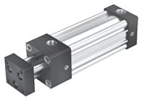
Tie Rod Cylinders |  |
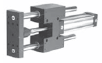
Guided Cylinders |
 |
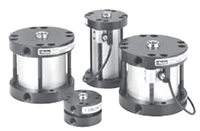
Round Body Cylinders |  |
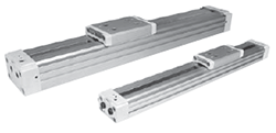
Rodless Cylinders |
 |
Compact Cylinders |
 |
 |
Engineering & Product Selection Information
Pneumatic Product Selection
- Pneumatic Actuators & Air Cylinders
- Pneumatic Cylinders
- Automation Products: rotary actuators, grippers, slide tables, rotary tables, escapement
- Actuator Accessories: Linear alignment couplers, flow controls, air oil tanks, rodlocks, electronic sensors, shock absorbers
Application Engineering Data
- Operating Principles and Construction
- Fluids and Temperature
- Push and Pull Forces
- Mounting Information
- Ports
- Tie Rod Supports, Stroke Data & Stroke Adjusters
- Mounting Classes
- Stop Tubing
- Stroke Selection Chart
- Deceleration Force and Air Requirements
- Cushion Ratings and Air Requirements
- NFPA Rod End Data and Piston Rods
- Modifications, Special Assemblies, Tandem Cylinders, Duplex Cylinders
- Rotary Actuator Torque Requirements
- Rotary Actuator Basic Equations
- Conversion Factors
