Cushion Rating and Air Requirements for Parker Air Cylinders
You can use the bore size and rod diameter of a Parker air cylinder to determine its cushion ratings by referring to the Air Cylinder Cushion Ratings Table below. If a simple circuit is used with no meter or speed control, use the "Rating with No Back Pressure" column values. if a mater out or speed control will be used, use the "Rating With Back Pressure" column values.
If the cushion rating found in the Air Cylinder Cushion Ratings table is greater than the number determined in the Kinetic Energy Graph, then the cylinder will stop the load adequately. If the cushion rating in the table is smaller than the number found in the Kinetic Energy Graph, then a larger bore cylinder should be used. In applications where back pressures exist in the exhaust lines, it is possible to exceed the cushion ratings shown in the table below. In these cases, specify in the order and advise the amount of back pressure.
(In general, if the cushion rating number from the Kinetic Energy Graph is greater than the cushion rating for a particular bore and rod diameter, other and external means of decelerating the load will be necessary for proper cylinder application. Parker options include shock absorbers, Par-Check hydraulic resistance units and NuCushion bumpers. Shock absorbers provide the greatest selection of decelerating products and many can be incorporated into the cap end of cylinders for retract stroke deceleration.)
4MA Air Cylinder Cushion Ratings Table
| Bore | Rod Dia. (mm) |
Rating with no back pressure |
Rating with back pressure |
| 1-1/2 | 5/8 | 8 | 14 |
| 1 | N/A | N/A | |
| 2 | 5/8 | 12 | 18 |
| 1 | 9 | 15 | |
| 2-1/2 | 5/8 | 14 | 20 |
| 1 | 14 | 19 | |
| 3-1/4 | 1 | 18 | 24 |
| 1-3/8 | 17 | 23 | |
| 4 | 1 | 20 | 27 |
| 1-3/8 | 20 | 26 | |
|
5 |
1 | 23 | 28 |
| 1-3/8 | 23 | 28 | |
|
6 |
1-3/8 | 26 | 31 |
| 1-3/4 | 26 | 31 | |
|
8 |
1-3/8 | 29 | 35 |
| 1-3/4 | 29 | 34 |
Inch Based Cylinders - Air Requirement Per Inch of Cylinder Stroke
The amount of air required to operate a cylinder is determined from the volume of the cylinder and its cycle in strokes per minute. This may be determined by using the folllowing formulae which apply to a single-acting cylinder (the air requirements for a double-acting cylinder is almost double that of a single-acting cylinder, except for the volume of the piston rod):
V= 3.1416 L D2/4
C= ƒV/1728
Where:
V = Cylinder volume, cu. in.
L = Cylinder stroke length, in.
D = Internal diameter of cylinder in.
C = Air required, cfm
ƒ = Number of strokes per minute
The air flow requirements of a cylinder in terms of cfm should not be confused with compressor ratings, which are given in terms of free air. If compressor capacity is involved in the consideration of cylinder air requirements, it will be necessary to convert cfm values to free air values. This relationship varies for different gauge pressures.
Thrust (lbs) = operating pressure x area of cylinder bore
(Note that on the "out" stroke, the air pressure is working on the entire piston area - on the "in" stroke, the air pressure works on the piston area less the rod area.)
Graph B2
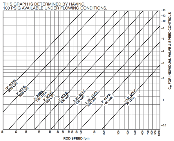
| Bore Size | 1-1/2" | 2" | 2-1/2" | 3-1/4" | 4" | 5" | 6" | 8" |
| Dynamic Thrust (lbs) | 88 | 155 | 240 | 410 | 620 | 980 | 1400 | 2500 |
| Static Thrust (lbs) | 177 | 314 | 491 | 830 | 1250 | 1960 | 2820 | 5020 |
Graph B3
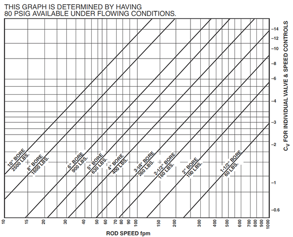
| Bore Size | 1-1/2" | 2" | 2-1/2" | 3-1/4" | 4" | 5" | 6" | 8" |
| Dynamic Thrust (lbs) | 60 | 100 | 160 | 260 | 400 | 630 | 900 | 1600 |
| Static Thrust (lbs) | 141 | 251 | 393 | 663 | 1000 | 1570 | 2260 | 4010 |
The graphs above can be used to select pneumatic components for dynamic cylinder applications - it is only necessary to know the force required, desired speed and the pressure which can be maintained at the inlet to the air preparation system. These graphs assume average conditions relative to air line sizes, system layout, friction, etc. At higher speeds, appropirate cushioning of cylinders may be necessary.
How to use these graphs:
1. Select the appropriate graph based upon the pressure that can be maintained to the system - Graph B2 for 100 psi and Graph B3 for 80 psi.
2. Determine the appropriate cylinder bore. Values underneath the diagonal cylinder bore lines indicate the maximum recommended dynamic thrust developed while the cylinder is in motion. The data in the table at the bottom of each graph indicates available static force applications in which clamping force is a prime consideration in determining cylinder bore. Consult the corresponding table to determine approximate thrust developed at a given operating pressure.
3. Read upward on the appropriate rod speed line to the intersection with the diagonal cylinder bore line. Read right from the intersection point to determine the required Cv off the valve and the speed controls. Both the valve and the speed controls must have this Cv.
The following examples illustrate how these charts and tables work:
Example 1: Assume that it is necessary to raise a 900-pound load 24 inches in two seconds. With 100 psi maintained at the inlet to the air preparation system, use Graph B2. The 5-inch bore cylinder is capable of developing the required thrust while in motionn. Since 24 inches in two seconds is equal to 60 fpm, read upward on the 60 fpm line to the intersection of the 5-inch bore diagonal line. Reading to the right indicates that the required valve and speed controls must each have a Cv of over 1.9.
Example 2: Assume similar conditions to example 1 except that the load is being moved in a horizontal plane with a coefficient of sliding friction of 0.2. Only a 180-pound thrust is now required (900 lb x 0.2). Consult Graph B3. The 2-1/2 inch bore cylinder will develop sufficient thrust and at 60 fpm requires a valve and speed control Cv of about 0.5.
Available Pneumatic Cylinder Styles
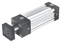 |
Tie Rod Cylinders | 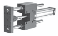 |
Guided Cylinders |
 |
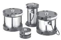
Round Body Cylinders | 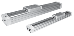 |
Rodless Cylinders |
 |
Compact Cylinders |
 |
 |
Engineering & Product Selection Information
Pneumatic Product Selection
- Pneumatic Actuators & Air Cylinders
- Pneumatic Cylinders
- Automation Products: rotary actuators, grippers, slide tables, rotary tables, escapement
- Actuator Accessories: Linear alignment couplers, flow controls, air oil tanks, rodlocks, electronic sensors, shock absorbers
Application Engineering Data
- Operating Principles and Construction
- Fluids and Temperature
- Push and Pull Forces
- Mounting Information
- Ports
- Tie Rod Supports, Stroke Data & Stroke Adjusters
- Mounting Classes
- Stop Tubing
- Stroke Selection Chart
- Deceleration Force and Air Requirements
- Cushion Ratings and Air Requirements
- NFPA Rod End Data and Piston Rods
- Modifications, Special Assemblies, Tandem Cylinders, Duplex Cylinders
- Rotary Actuator Torque Requirements
- Rotary Actuator Basic Equations
- Conversion Factors
